Close

Download
2.2 SPUR GEARS
The most common toothed gears are the so-called spur gears, which have their teeth radially on the external (or internal) surface of the gear. In particular, the spur gears are used to transmit the rotation motion between two parallel axes (or shafts).
The data of the maximum torque shown in the tables of the technical data sheet are the result of a cross between the theoretical calculations and the experimental data obtained in the laboratory.
Theoretical calculations are based on the Lewis formula. According to this formula the tooth (Fig.2), considered as a shelf wedged on the gear, does not yield under the action of the force (F) (considered as static force) transmitted by the gears. This theory is based on the following hypotheses:
- the stress of the total force (F) on the tooth is considered as applied to the tip of the tooth itself
- the radial component of the force (Fr) which determines a compression stress on the tooth is considered negligible; it follows that the component of force (F) that determines the bending of the tooth is the only one considered and, for simplicity, will have the same value as the tangential force (Fr) on the pitch circle
- for the calculation the most unfavorable situation is taken into consideration, with only one pair of teeth engaged
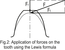
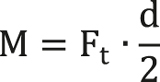
The force (Ft) is then correlated to the torque (M) by means of the pitch diameter:
The experimental data has been obtained by laboratory tests and checked with software taking into consideration the VDI 2736 guideline for the design of technopolymer toothed gears. The tests have been carried out in continuous operation and at a speed of 100-150 rpm without any lubrication, to test the most severe conditions.
The torques in the tables of the technical data sheets provide a rough information and cannot be considered valid for every possible application. The operating conditions (rpm, working temperatures, coupling with transmission elements made of different materials, lubricated or dry conditions, service factor, etc.) strongly influence the performance.
The design engineer must take into account the actual conditions of use, different from those of the laboratory.
-
Generals
-
1. Plastic materials
- 1.1 Mechanical strength
- 1.2 Thermal resistance
- 1.3 Strength and surface hardness
- 1.4 Resistance to chemical agents
- 1.5 Resistance to atmospheric agents and uv rays
- 1.6 Flame resistance
- 1.7 Electrical properties
- 1.8 Surface finish and cleanability
- 1.9 Compliance with international standards
- 1.10 Competence of Elesa+Ganter technical department
- 2. Metal materials
- 3. Other materials
- 4. Machining tolerances
- 5. Fixed handles
- 6. Assembly measures
- 7. Special executions
- 8. Colours
- 9. Test values
-
10. Technical tables
- 10.1 Conversion tables
- 10.2 DIN 79 Square holes and shafts
- 10.3 DIN 6885 Keyways
- 10.4 GN 110 and GN 110.1 Transversal holes
- 10.5 DIN 13 ISO Metric threads
- 10.6 DIN 228 Cylindrical GAS-BSP threads
- 10.7 DIN EN ISO 898-1 | DIN EN 20898-2 Strenght values
- 10.8 DIN ISO 286 ISO-Fundamental tolerances
- 10.9 IP Protection Classification
- 10.10.1 PFB | PRB Thread locking with jamming action Polyamide patch coating/ Polyamide complete coating
- 10.10.2 MVK Thread locking gluing Micro encapsulation precote 80 (red)
- 10.11 Stainless Steel characteristics
- 10.12 Surface treatments
- 10.13 Carbon steel, zinc alloys, aluminium, brass characteristics
- 10.14.1 Duroplast, elastomer, technopolymer and rubber characteristics
- 10.14.2 Duroplast, elastomer, technopolymer and rubber characteristics
- 10.14.3 Duroplast, elastomer, technopolymer and rubber characteristics
- 10.15 Load ratings U-Handles
- 10.16 Load ratings metal hinges
- 10.17 Strength of indexing plungers
- 10.18 Assembly sets GN 965 and GN 968
- 11. Vibration-damping elements
-
1. Plastic materials
- Hygienic design
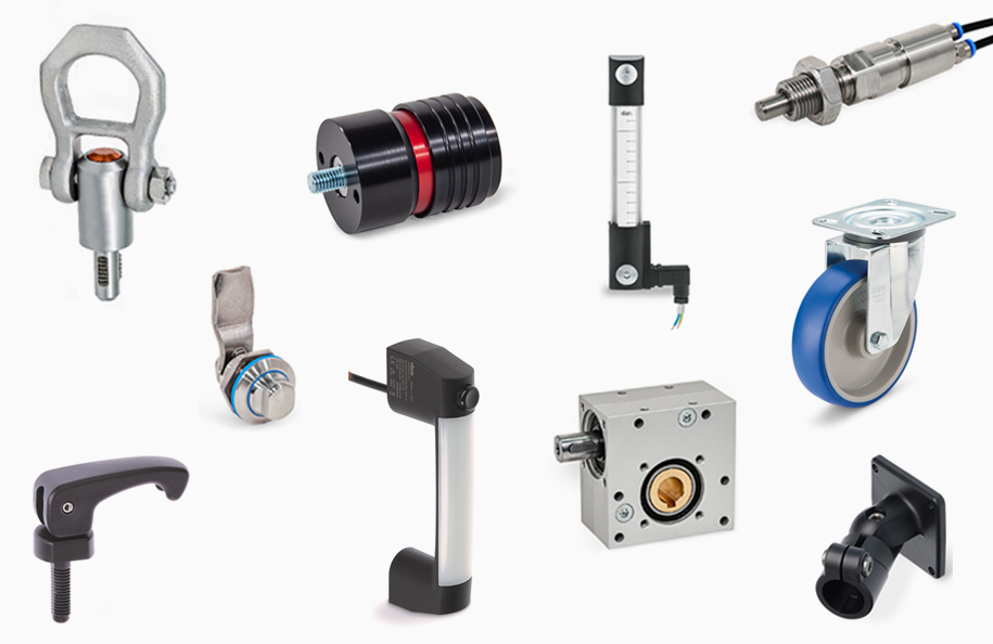
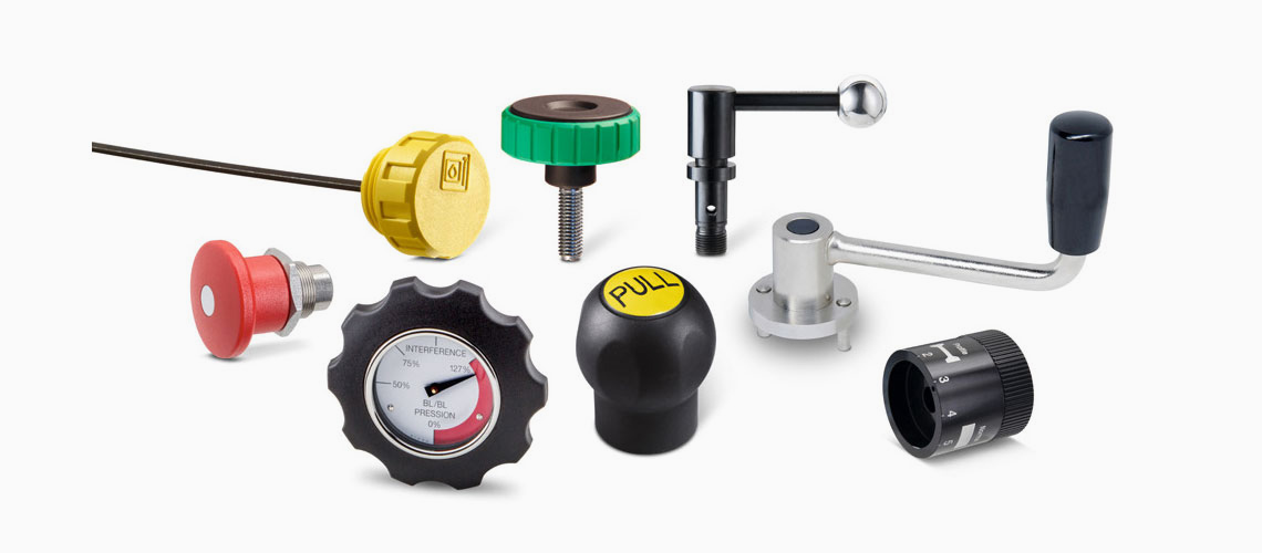
- Operating Elements
- Clamping knobs
- Control elements
- Rotary controls
- Indexing elements
- Joints
- Transmission elements
- Levelling elements
- Hinges
- Latches
- Toggle, power and hook clamps
- Accessories for hydraulic systems
- Tube clamp connectors
- Castors and wheels
- Magnets
- Conveyor components
- Linear slides
- Vibration mounts
- Vacuum components
- Elastomer springs